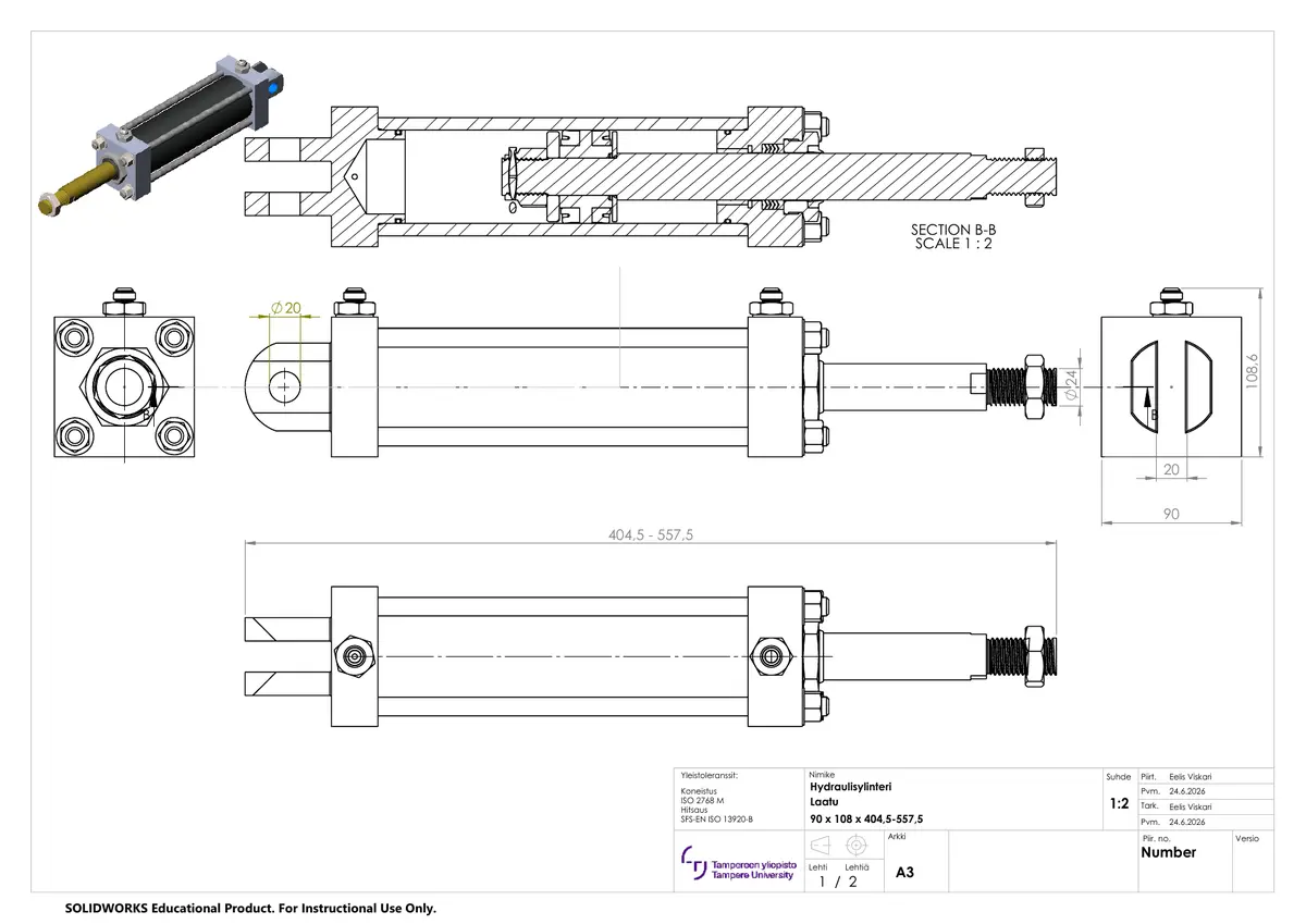
Hydraulic cylinder
Assembly views, longitudinal section, principal dimensions and bill of materials.
Mechanical design · Course project
A complete SolidWorks project covering part modelling, mechanical design, assembly integration, manufacturing documentation and motion.
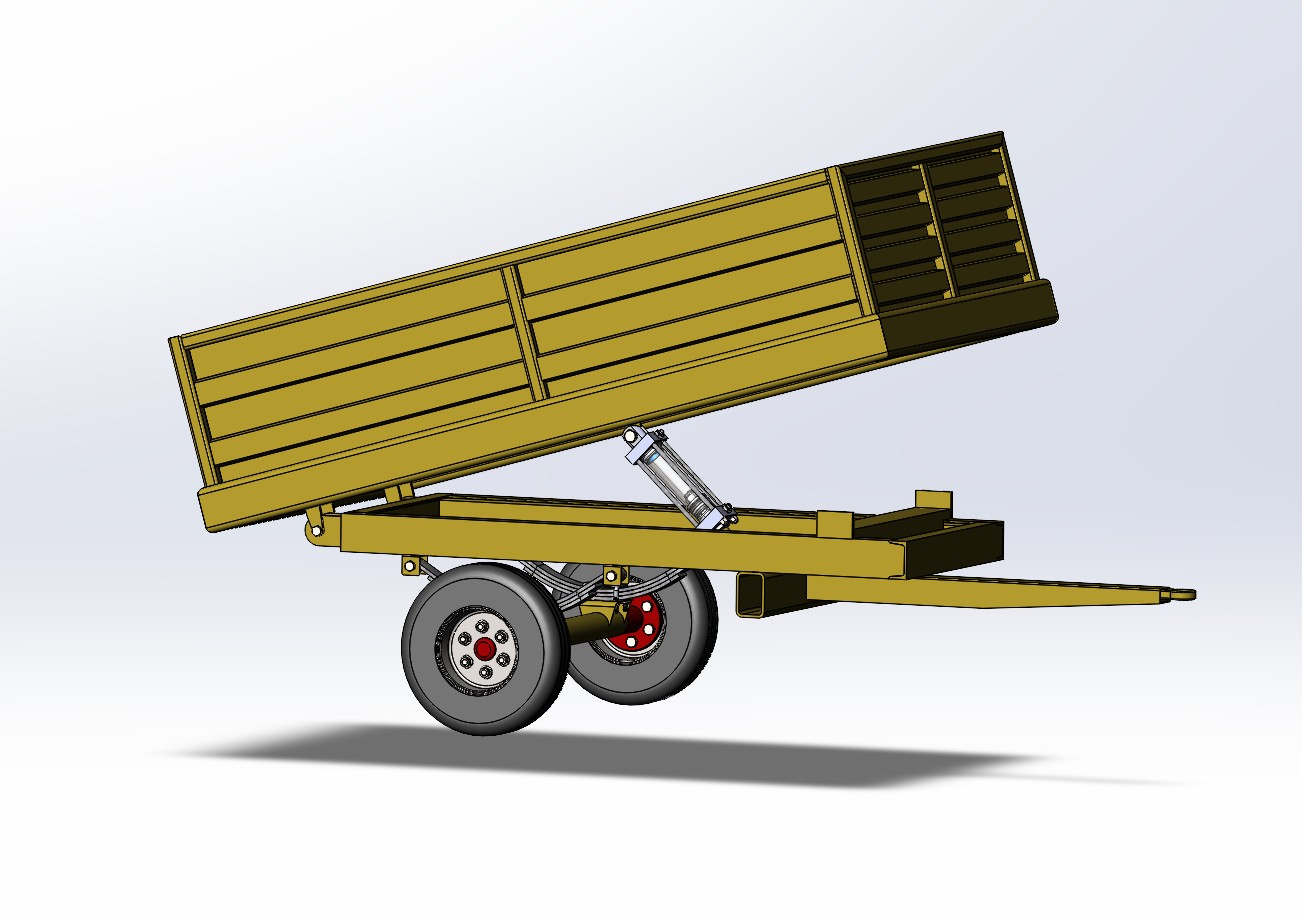
Project overview
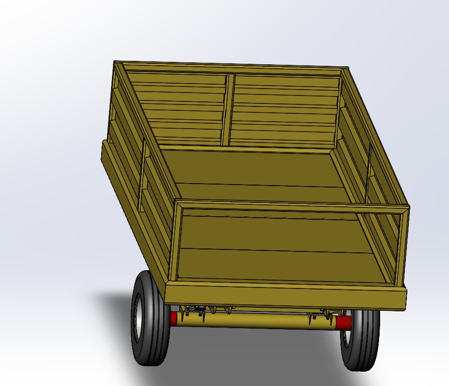
The objective was to learn how to model parts, create technical drawings and use SolidWorks across a complete engineering workflow. Instead of focusing on a single component, the project required a functional assembly with multiple frames, a tandem axle, a trailer body and a hydraulic tipping mechanism.
I modelled and assembled the project independently. The leaf springs, wheels and axle mounting components were sourced from an existing model. Every other component was either recreated from manufacturing documentation or designed by me.
Design details
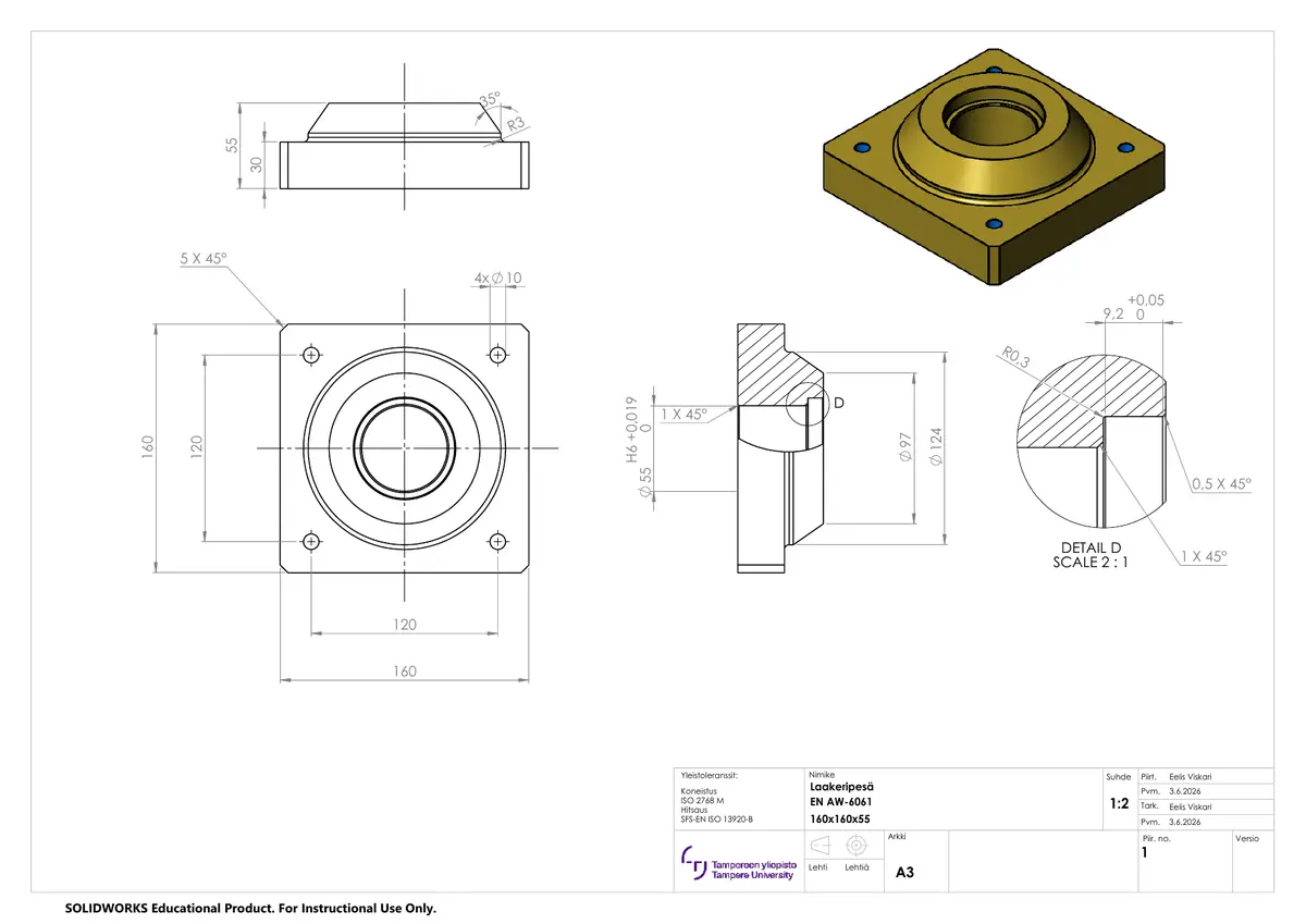
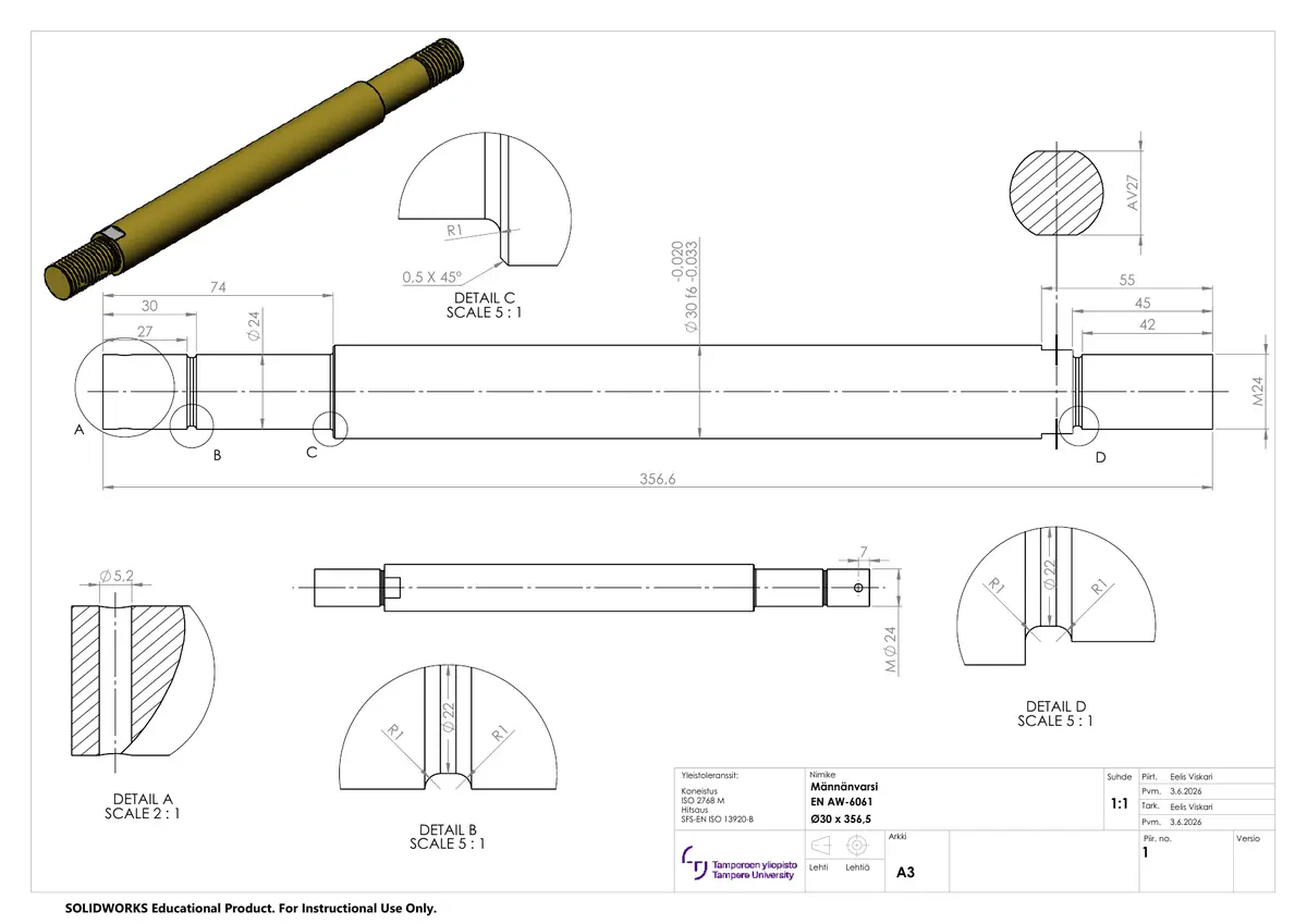
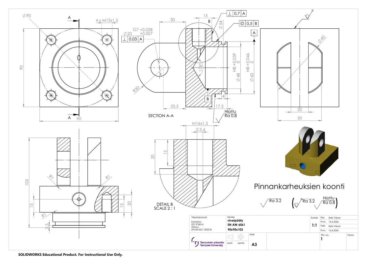
My technical drawings
I created these A3 manufacturing drawings from my SolidWorks models as part of the course project. The original PDFs show my dimensioning, tolerances, section views and component details.
Assembly views, longitudinal section, principal dimensions and bill of materials.
Engineering process
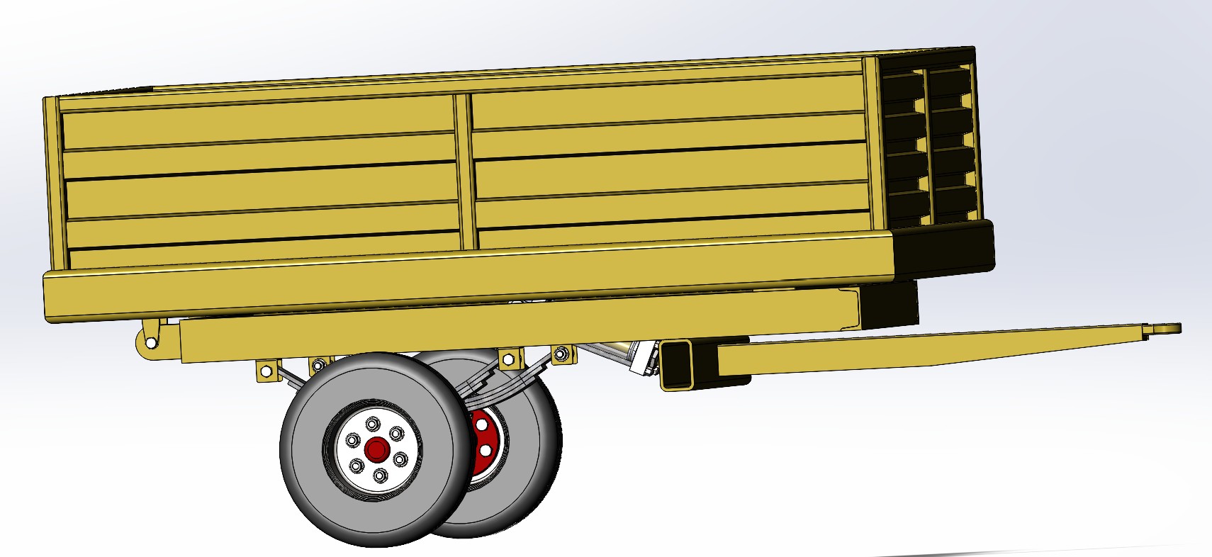
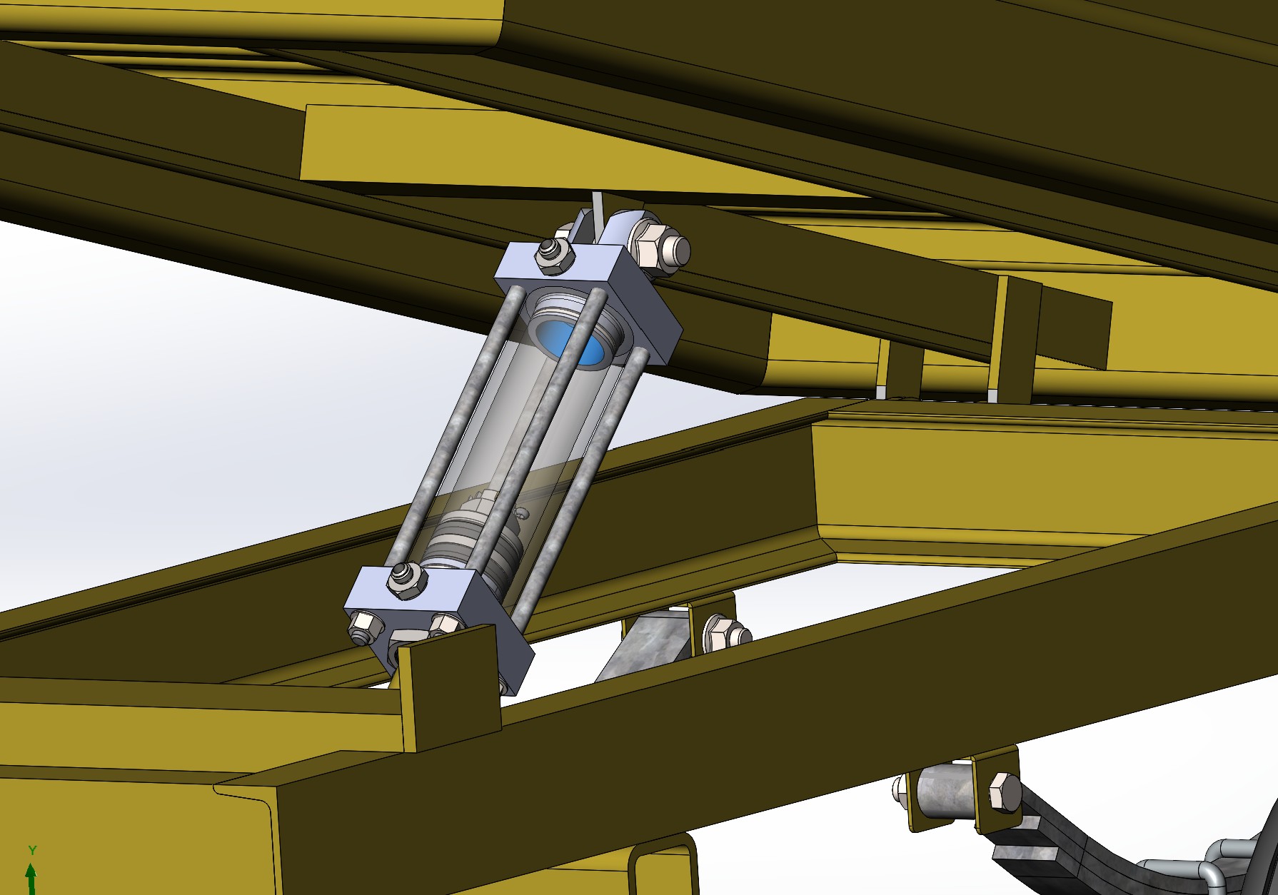
The most difficult phase was bringing the frames, axle, trailer body and hydraulic cylinder together into one working SolidWorks assembly.
I worked through component relationships and mate behaviour over several days. The size of the assembly also required careful management of performance and software stability.
The completed assembly moves through its tipping range and connects the structural design, axle system and hydraulic mechanism into one model.
Assembly motion
What I learned
The project gave me practical experience in SolidWorks part modelling, multi-level assemblies and original mechanical design. I also learned to turn models into manufacturing documentation and exploded views.
Most importantly, I learned how small modelling and mate decisions affect an entire mechanical system. Solving the assembly problems required persistence, structured troubleshooting and repeated testing.